Friday, March 27, 2020

,
16 Channel DTMF MT8870 Audio Decoder Board Phone Voice Decoding Controller for Smart Home Automation
16 Channel DTMF MT8870 Audio Decoder Board Phone Voice Decoding Controller for Smart Home Automation16 Channel DTMF MT8870 Audio Decoder Board Phone Voice Decoding Controller for Smart Home Automation16 Channel DTMF MT8870 Audio Decoder Board Phone Voice Decoding Controller for Smart Home Automation


Specifications:  
 
DC Power Supply Voltage:4.5V-5.5V
Operating Temperature : -40- 85 °C 
IO Drive : Sink Current (Low level drive) 20mA,source current(High level drive) 270uA 
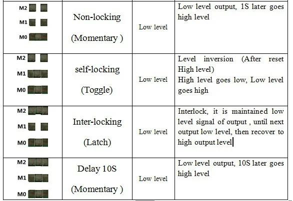
16 Channel selectable high and low level output. 
8 kinds of Mode selection
PCB Size : 50 x 20 mm
 
Overview: 
 
This decoding module is for mobile and fixed telephone voice dialing decoding function , has 16 channels, 8 kinds of selectable output function, and leads to STD signal to use as a microcontroller interrupt signal, very convenient to embed all kinds for mobile and fixed telephoneremote remote control, remote control decoding key value. 12 channels outputs decode mobile and fixed telephone keys (0-9, * #).Another 4 channels output(ABCD) can use "DTMF Dial" Software control.


Package Included: 
 
1 x 16 Channel DTMF Decoder Module
1 x Male to Male Audio Cable (3.5mm jack )


16 Channel DTMF MT8870 Audio Decoder Board Phone Voice Decoding Controller for Smart Home AutomationSee detail


,
TB293 7W USB DC to DC 5V to 6V 9V 12V 15V Adjustable Output Converter Step Up Boost Module for LED Motor Fan
TB293 7W USB DC to DC 5V to 6V 9V 12V 15V Adjustable Output Converter Step Up Boost Module for LED Motor FanTB293 7W USB DC to DC 5V to 6V 9V 12V 15V Adjustable Output Converter Step Up Boost Module for LED Motor FanTB293 7W USB DC to DC 5V to 6V 9V 12V 15V Adjustable Output Converter Step Up Boost Module for LED Motor Fan


Description: 
 
Input voltage : 3~6V
Output voltage : 6-15.5V
Maximum input current :  1.4A
Long-term work Current : 1A
Conversion efficiency : 79-90%  
Input Interface :  USB  Male
Ouput Interface :  2 PIN  XH2.54 
Power :  Maximum 7W
Working frequency : 1.0MHz
Operating temperature : -40 to +85 ℃
Size: 47.5 x 16mm
  
Applications:
 
6-15V Low Power Motor
6-15V LED Lighting
Hard drive power supply
9V 12V 15V Routers and network equipment
Wireless communication equipment
315M 433M Wireless remote controller
   
Attention :
 
1. Input voltage can not be greater than the maximum input range.
2. Output power can not be greater than the maximum load for a long time.
3. Input power must be greater than the output power, because the power consumption of the module itself.

Modify Parameter Description:   
 
1.4A current limiting resistor,Remove the resistance, the maximum input current can reach 2A.
But IC have "Over Temperature Protection" Function.It will turn off the power MOSFET automatically when the internal junction temperature is over 150 Degrees Celsius. The power MOSFET wake up when the junction emperature drops 30 Degrees Celsius under the OTP threshold temperature
 
aeProduct.getSubject()
 
Package Included:
 
1 x USB 5V to 6-15.5V DC DC Converter
1 x Cable


TB293 7W USB DC to DC 5V to 6V 9V 12V 15V Adjustable Output Converter Step Up Boost Module for LED Motor FanSee detail


,
CE032 DC 5V 6V 9V 12V Motor Reversible Controller Time Adjustable Delay DPDT Relay Switch 2A 5000S
CE032 DC 5V 6V 9V 12V Motor Reversible Controller Time Adjustable Delay DPDT Relay Switch 2A 5000SCE032 DC 5V 6V 9V 12V Motor Reversible Controller Time Adjustable Delay DPDT Relay Switch 2A 5000SCE032 DC 5V 6V 9V 12V Motor Reversible Controller Time Adjustable Delay DPDT Relay Switch 2A 5000S


Specifications:
   
Operating voltage: DC 5-12V(5V 6V 9V 12V)
Operating current: 5V,forward 4ma, reverse: 36ma;12V, Forward 6ma, reverse: 44ma;
Load voltage: DC 1-48V OR AC 85-265V
Load current: Maximum 2A
Forward maximum time: 5000 seconds, 0.1 seconds step
Reverse maximum time: 5000 seconds, 0.1 seconds step
By "Time multiple selection" setting,The maximum delay of up to 40,000 seconds.(short-circuited pad)
Size: 54 x 22 x 15 mm
 

aeProduct.getSubject()

aeProduct.getSubject()


How to Use:
 
VIN connected to the positive of power supply , GND connected to the negative of power supply;
P+ connected to the positive of Motor power supply, P- connected to the negative of Motor  power supply;
M + M- are connected to both ends of the motor
 
After power, D1 flashes 3 times, D2 off, M+ output positive, M- output negative, motor forward; after a time delay T1, D2 on, M+ output negative, M- output positive, motor reversal; after a time delay T2, D2 off, M+ output positive, M- output negativ, motor forward;and so on.
 
T1: indicates motor Forward delay time, default 0.1-5000 seconds adjustable (step 0.1 seconds)
T2: indicates motor Reverse delay time, default 0.1-5000 seconds adjustable (step 0.1 seconds)
 
By "Time multiple selection" setting,The maximum delay of up to 40,000 seconds
 
How to Set Up:

 
aeProduct.getSubject()
 
1. After power, D1 3 blinks, Enter the "work mode"
D2 on Reversal,D2 Off Forward
2. Press and hold the Key for 2 seconds,D1 on,enter the "setup mode"
D2 off, It's forward "setup mode"
3. In forward "setup mode", the continuous trigger KEY twice ,D1 off,entry "Standby timer mode"
4. In the "Standby timer mode" ,trigger KEY start timing(entry "Timing Mode")
D1 flashing said it is timing("Timing Mode")
Trigger KEY again to stop the clock(exit "Timing Mode")
D1 flashing time is forward time(T1) 
5. Press and hold the Key for 2 seconds,D2 on,enter the Reverse "setup mode"
6. In Reverse "setup mode", the continuous trigger key twice ,D1 off,entry "Standby timer mode"
7. In the "Standby timer mode" ,trigger KEY start timing(entry "Timing Mode")
D1 flashing said it is timing("Timing Mode")
Trigger KEY again to stop the clock(exit "Timing Mode")
D1 flashing time is Reverse time(T2) 
So far, forward time(T1) and reverse time(T2) is set up
Re-power in "work mode"
 
Package Included:
 
1 x CE032 DC 5V 6V 9V 12V Motor Reversible Controller
 

aeProduct.getSubject()

aeProduct.getSubject()


CE032 DC 5V 6V 9V 12V Motor Reversible Controller Time Adjustable Delay DPDT Relay Switch 2A 5000SSee detail


,
Copy Board Failure Board Safe Burglar Alarm Electronic Competition Training DIY Kit
Copy Board Failure Board Safe Burglar Alarm Electronic Competition Training DIY KitCopy Board Failure Board Safe Burglar Alarm Electronic Competition Training DIY KitCopy Board Failure Board Safe Burglar Alarm Electronic Competition Training DIY Kit


Features:

The safe anti-theft safety circuit, theft of thieves, fire and smuggling can be alarmed by alarm to prevent loss in time.

Working principle
 
1.Sensor
Y1 vibration sensor (piezoelectric sensor)
BZ mercury switch sensor
RT temperature sensor
 
2. Detection circuit

(1) Pry detection alarm circuit
When the safe is subjected to vibration, the piezoelectric sensor Y1 will sense the voltage signal, which will be amplified by VT1 and then amplified, and will be transmitted to pin 3 of the dual D trigger U5. foot.
(2) sport detection alarm circuit
It can detect whether the safe is tilted due to moving. When tilting occurs, the mercury sensor BZ is turned on, and a high-level signal is transmitted to pin 5 of the OR circuit U3.
(3) Flame cutting detection alarm circuit
The thief opened the safe by means of flame cutting, the thermistor RT detected a temperature rise, and the comparator U4 output a high-level signal to transmit to the 4 pin of the OR circuit U3.
3.Three OR gate circuit
As long as one of the A pins of U3 is high, its "6" pin outputs a high level and charges capacitor C9 through D4 and R11. The voltage of the "11 ~ 13" pins of B or gate of U3 increases Then make "10" pin output high level.
4. Sound alarm circuit
The high level of pin 10 of U3 turns on the transistor VT2, the relay JK1 engages, and the alarm signal BL1 sends a warning signal (local alarm); the base of the transistor VT3 becomes high because of the relay JK1's attracting ( When the relay JK1 is not activated. The triode VT3 base is extremely low level), VT3 is turned on, JK2 is activated, and the alarm device BL2 issues an alarm signal (remote alarm). As long as there is one of these signals, a loud alarm can be issued and delayed for a period of time.


Package includes:

1 x Alarm Electronic Competition Training DIY Kit


Copy Board Failure Board Safe Burglar Alarm Electronic Competition Training DIY KitSee detail


,
150pcs Terminal Connector Direct-pin Bare Wire Connector Terminal
150pcs Terminal Connector Direct-pin Bare Wire Connector Terminal150pcs Terminal Connector Direct-pin Bare Wire Connector Terminal150pcs Terminal Connector Direct-pin Bare Wire Connector Terminal


Specification:
 
Type: Terminal
Working frequency: low frequency
Application: Wire Cable
Shape: Bar
Characteristics: Fire resistance / Flame retardant
Contact material: Copper
Insulator material: Plastic

Package includes:
 
1 x 150PCS JST-XH  Terminal Connector 2-5PIN


150pcs Terminal Connector Direct-pin Bare Wire Connector TerminalSee detail


Search This Blog

Follow Us @soratemplates